In the field of medical imaging, the process of reconstructing images from projections plays a crucial role, particularly in technologies such as CT scans. This process, often referred to as back-projection, involves the transformation of 1D absorption data into 2D images.

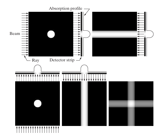
The figures provided illustrate the principles behind back-projection, starting with a simple object (like a circular shape) and progressively adding more projections at various angles.
The technique begins by capturing the absorption profile of an object using parallel beams and detector strips. By rotating the source-detector pair and projecting the absorbed data onto a 2D plane, an image is gradually reconstructed. As more projections are added, the accuracy of the image improves, but it also introduces a blurring effect, which requires advanced techniques to resolve.
Through the example of reconstructing simple objects with differing absorption properties, such as those shown in the images, we can explore the foundational concepts of image reconstruction. These concepts are essential for understanding more complex applications in medical diagnostics and imaging technology.
Principles of Computed Tomography (CT)

Computed Tomography (CT) is a widely used imaging modality that combines X-ray measurements from different angles to produce cross-sectional images of a patient’s body. It plays a crucial role in medical diagnostics, allowing doctors to visualize internal organs, bones, and tissues in great detail. CT reconstruction involves the application of advanced mathematical techniques to convert raw projection data (obtained through X-ray measurements) into images that can be interpreted by medical professionals.
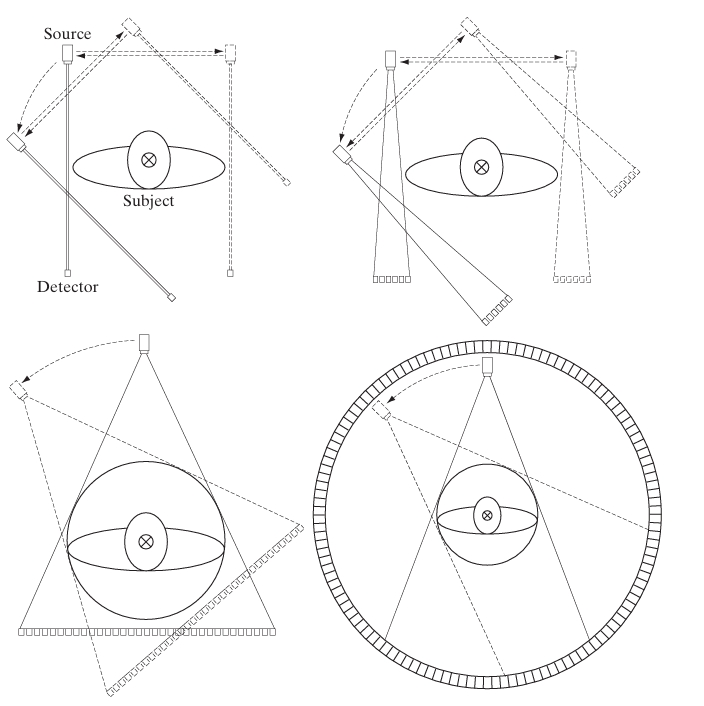
In a typical CT scan, an X-ray source rotates around the patient, projecting X-rays at various angles. Detectors measure the intensity of the X-rays after they pass through the patient’s body. Since different tissues (e.g., bones, muscles, and organs) absorb X-rays to varying degrees, the measurements recorded by the detectors provide information about the internal structure of the body. The goal is to reconstruct a series of 2D images (slices) from these measurements, which together can form a detailed 3D representation of the scanned region.
Mathematically, the problem of CT image reconstruction can be described as an inverse problem, where the challenge is to infer the internal structure (the image) from the observed data (the X-ray projections).
Mathematical Foundations of CT
1. The Radon Transform
The central mathematical tool in CT reconstruction is the Radon transform, which represents the projection of an object’s internal structure along a particular angle. If we define the object as a 2D function representing the X-ray attenuation at each point, the Radon transform gives the line integral of this function along lines passing through the object at various angles.
For an image , the Radon transform at an angle and distance from the origin is given by:
The Radon transform essentially provides the “projection” of the image along lines perpendicular to the vector .
In CT, these projections are measured at multiple angles around the patient. The goal is to recover the original image from the set of projections taken over different angles .
2. Fourier Slice Theorem
One of the most fundamental mathematical principles used in CT reconstruction is the Fourier Slice Theorem (also known as the Central Slice Theorem). This theorem provides a link between the projections of an object and its representation in the frequency domain.
The Fourier Slice Theorem states that the 1D Fourier transform of a projection is equivalent to a slice of the 2D Fourier transform of the image along a line at the same angle . In other words, the Fourier transform of the Radon transform of the image gives the values of the 2D Fourier transform of the image along radial lines in the frequency domain.
Mathematically:
where is the 1D Fourier transform of the projection, and is the 2D Fourier transform of the image. The coordinates are frequency-domain variables related to the angle .
Using the Fourier Slice Theorem, it becomes possible to build the 2D Fourier transform of the image by combining the 1D Fourier transforms of the projections obtained at different angles. Once the 2D Fourier transform is assembled, the inverse Fourier transform can be applied to recover the original image.
3. Filtered Back Projection (FBP)
The most commonly used reconstruction algorithm in CT is Filtered Back Projection (FBP). FBP is a two-step process that uses both back projection and filtering techniques to reconstruct an image from the projection data.
Back Projection: The first step of FBP is back projection, which essentially smears the projection data across the image space. For each projection, the values along the corresponding X-ray paths are spread evenly across the image. However, back projection alone tends to blur the reconstructed image, especially near the center.
Mathematically, the back-projected image is given by summing the projections at all angles:
where .
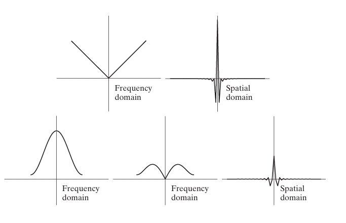
Filtering: To correct the blurring introduced by back projection, the projections are first filtered in the frequency domain using a high-pass filter. This step amplifies the higher-frequency components of the image, which are necessary for preserving sharp edges and fine details.
The filtered back projection formula is:
where is the filter function, typically a ramp filter, applied in the frequency domain.
FBP is computationally efficient and widely used in clinical CT imaging, although it has limitations when the data is noisy or incomplete.
4. Iterative Reconstruction Techniques
While FBP is fast and effective for well-sampled, high-quality data, iterative reconstruction techniques are more flexible and robust in handling noisy or incomplete data. These methods iteratively refine the reconstructed image by comparing the measured projections to those generated from the current image estimate and adjusting the image accordingly.
Two popular iterative reconstruction techniques are:
Algebraic Reconstruction Technique (ART): ART formulates the reconstruction problem as a system of linear equations, where each equation corresponds to a line integral (a projection). The image is updated iteratively by solving these equations using methods like least-squares optimization.
The update rule in ART is:
where is the current estimate of the image, is the measured projection data, is the projection operator, and is a relaxation parameter controlling the step size.
Simultaneous Iterative Reconstruction Technique (SIRT): SIRT simultaneously updates the image using information from all projections in each iteration. This method converges more slowly than ART but is more stable and handles noisy data better.
The SIRT update rule is:
where is the transpose of the projection operator .
5. Regularization and Sparse Reconstruction
CT image reconstruction can suffer from noise and artifacts, particularly in low-dose scans or when there are few projections. Regularization techniques are used to improve the quality of the reconstruction by introducing prior knowledge or constraints into the reconstruction process.
Tikhonov Regularization: Adds a smoothness constraint to the reconstruction to reduce noise. The regularized reconstruction problem is:
where is a regularization parameter that controls the trade-off between data fidelity and smoothness.
Total Variation (TV) Regularization: Promotes piecewise smoothness, preserving edges while suppressing noise. TV regularization is particularly useful in sparse reconstruction scenarios, where the number of projections is limited.
The TV regularization problem is:
where controls the strength of the regularization.
6. Sparse-View CT and Compressed Sensing
With advances in compressed sensing, it has become possible to reconstruct high-quality images from fewer projections, significantly reducing the radiation dose. Compressed sensing exploits the sparsity of images in certain transform domains (such as wavelets) to reconstruct images from undersampled data.
The mathematical formulation of compressed sensing-based reconstruction is:
where is a sparsifying transform (e.g., wavelet transform) and denotes the -norm, which promotes sparsity.
Example: Medical CT Reconstruction
In medical applications, CT scanners rotate around the patient, capturing X-ray projections at many different angles. These projections are then used to reconstruct cross-sectional images, allowing doctors to visualize internal structures in great detail. For example, in a chest CT scan, the system captures multiple projections of the lungs and thorax, and the FBP algorithm reconstructs the 2D image slices that can reveal diseases like lung cancer or pneumonia.
Reconstruction Using Parallel-Beam Filtered Back Projections

In computed tomography (CT), parallel-beam filtered backprojection is a fundamental algorithm used to reconstruct images from projections. This method is widely employed for 2D image reconstruction when projections are taken from parallel X-ray beams at multiple angles around the object. The core idea of backprojection is to take the measured projection data from different angles and “project” them back onto the image space. To address artifacts and blur introduced by simple backprojection, a filtering step is applied before backprojection to sharpen the image.
1. Parallel-Beam Projections
In parallel-beam geometry, a series of X-ray beams is sent through an object at a fixed angle. The beams are all parallel to each other, and detectors measure the intensity of the X-rays after they pass through the object. The result is a projection of the object along that particular angle.
The projection at angle , denoted by , represents the sum of the object’s attenuation values along lines parallel to the X-ray beams. Mathematically, this can be expressed using the Radon transform of the object function as:
where is the projection angle, and is the distance of the line from the origin.
To reconstruct the original image , we collect projections at different angles , typically ranging from 0 to 180 degrees.
2. Backprojection
Backprojection is a technique that uses the projection data to distribute the measured values across the image plane. For each projection at an angle , the measured values are spread along the lines (rays) corresponding to that angle. The contributions from all projections are summed to create a rough approximation of the image.
Mathematically, backprojection can be written as:
where .
However, this simple backprojection often leads to a blurred image, especially near the center, because it equally distributes the measured intensity across the entire line, leading to oversmoothing of sharp edges.
3. Filtered Backprojection (FBP)
To overcome the blurring effects of simple backprojection, a filtering step is introduced before the backprojection process. This is the key idea behind Filtered Backprojection (FBP). The filtering process compensates for the fact that simple backprojection overemphasizes low-frequency components of the image, which leads to a blurred result. A high-pass filter is applied to correct this imbalance and restore the sharpness of the image.
The Filtering Process
The filtering step is done in the frequency domain. The projection is first Fourier-transformed to convert it from the spatial domain to the frequency domain:
Here, is the frequency variable, and is the Fourier transform of the projection data. Next, a filter is applied to the Fourier-transformed data. The most common filter used is the ramp filter, which amplifies high-frequency components. The ramp filter in the frequency domain is defined as:
The filtered projection is then obtained by multiplying the Fourier-transformed projection by the ramp filter:
Finally, the inverse Fourier transform is applied to convert the filtered projection back to the spatial domain:
Backprojection of Filtered Projections
Once the projections are filtered, they are backprojected to form the final image. The filtered backprojection (FBP) algorithm is expressed mathematically as:
This process results in a much sharper image compared to unfiltered backprojection, as the high-frequency components critical for image edges are preserved.
4. Mathematical Example of Parallel-Beam FBP
Let’s assume we have an object represented by the function , and we collect parallel projections at different angles . To reconstruct the object:
Obtain Projections: Measure the projection for each angle .
Fourier Transform: Compute the Fourier transform of each projection.
Apply the Ramp Filter: Multiply the Fourier transform of the projection by the ramp filter .
Inverse Fourier Transform: Apply the inverse Fourier transform to obtain the filtered projections .
Backproject: Finally, backproject the filtered projections by integrating over all projection angles to reconstruct the image .
5. Advantages and Limitations of FBP
Advantages:
- Computational Efficiency: FBP is computationally fast and widely used in practice due to its simplicity and speed.
- Accuracy with Complete Data: When the data is noise-free and adequately sampled, FBP produces high-quality images.
Limitations:
- Sensitivity to Noise: FBP is sensitive to noise in the projection data. Since the ramp filter amplifies high-frequency components, noise in the projections can lead to artifacts in the reconstructed image.
- Inaccuracy with Sparse Data: If the number of projections is limited, FBP may produce images with streak artifacts or insufficient detail. In such cases, iterative reconstruction methods or regularization techniques are often preferred.
6. Applications of Parallel-Beam FBP
Parallel-beam FBP is used in various imaging fields:
- Medical Imaging (CT): It is a standard method in clinical CT scanners, where detailed images of the body’s internal structures are reconstructed from X-ray projections.
- Industrial Tomography: Used for nondestructive testing of materials and objects by reconstructing cross-sectional images from X-ray projections.
- Astrophysics and Geophysics: It helps reconstruct 2D images from projections in scientific fields dealing with astronomical or geological structures.
Reconstruction Using Fan-Beam Filtered Back Projections

Fan-beam filtered backprojection is a widely used method in computed tomography (CT) for reconstructing images from projections when X-ray beams are arranged in a fan-like shape. This differs from parallel-beam geometry, where X-ray beams are parallel. Fan-beam geometry is commonly used in modern CT scanners because it allows for faster data acquisition by using a rotating X-ray source and detector array that sweeps around the patient. The fan shape arises naturally from the fact that the X-ray source is fixed at a single point and the beams diverge as they move toward the detectors.
1. Fan-Beam Geometry
In fan-beam CT, the X-ray source is located at a point, and the X-ray beams spread out in a fan shape as they travel towards a circular array of detectors. As the source and detectors rotate around the object (typically a patient in medical imaging), multiple projections are captured from different angles.
Each projection corresponds to the attenuation of the X-rays as they pass through the object along the fan-shaped paths. The challenge is to reconstruct the original image of the object from these projections.
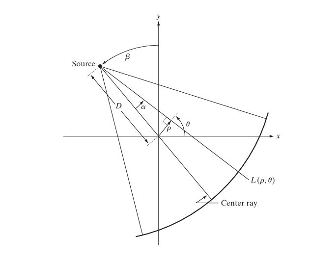
Fan-beam projections are denoted as , where:
- is the rotation angle of the X-ray source around the object.
- is the fan angle, which represents the angle of the X-ray beam relative to the central ray (the ray directly from the source to the center of the detector array).
2. Relation Between Fan-Beam and Parallel-Beam Projections
One of the key steps in fan-beam filtered backprojection is converting fan-beam projections into equivalent parallel-beam projections. This is important because many CT reconstruction algorithms, such as filtered backprojection, are based on parallel-beam geometry.
For a fan-beam projection , the corresponding parallel-beam projection at the same rotation angle can be obtained using the following relation:
where:
- is the distance from the X-ray source to the center of rotation.
- is the distance along the line perpendicular to the parallel beams.
Once the fan-beam projection has been converted into the equivalent parallel-beam projection, the parallel-beam filtered backprojection algorithm can be applied. However, additional weighting and filtering steps are necessary due to the non-uniform sampling of the fan-beam projections.
3. Fan-Beam Filtered Backprojection (FBP)
The Fan-Beam Filtered Backprojection (FBP) algorithm consists of three main steps: filtering, reweighting, and backprojection.
Step 1: Filtering
Just like in parallel-beam filtered backprojection, the first step is to apply a filtering operation to the fan-beam projections. The filtering process is carried out in the frequency domain using a ramp filter. The fan-beam projection is first Fourier-transformed to the frequency domain:
where is the frequency variable. The ramp filter, denoted , amplifies the high-frequency components of the projection to compensate for the smoothing effect of simple backprojection:
The filtered projection is then obtained by multiplying the Fourier-transformed projection by the ramp filter:
Finally, the inverse Fourier transform is applied to convert the filtered projection back to the spatial domain:
Step 2: Reweighting
Since fan-beam projections are non-uniformly sampled (the X-rays diverge from the source), a reweighting step is necessary to ensure accurate reconstruction. Each projection is multiplied by a weighting factor to account for the varying distances between the source and the detector elements.
The reweighting factor is proportional to the cosine of the fan angle :
This step ensures that the contributions of X-rays at different angles are correctly balanced during the reconstruction.
Step 3: Backprojection
After filtering and reweighting, the next step is backprojection. In this process, the filtered and reweighted projections are backprojected across the image space. For each projection angle , the values of the projection are spread along the corresponding fan-shaped paths.
The backprojection for a fan-beam projection is given by:
where is the fan angle that corresponds to the X-ray path intersecting the point in the image. The integral sums the contributions from all projections at different angles .
4. Mathematical Example of Fan-Beam FBP
Let’s consider a simple example of reconstructing an image using fan-beam FBP. The steps are:
Fan-Beam Projections: Measure the fan-beam projections for a set of projection angles .
Fourier Transform and Filtering: Apply the Fourier transform to each projection, multiply by the ramp filter, and then apply the inverse Fourier transform to obtain the filtered projections.
Reweighting: Multiply the filtered projections by the cosine of the fan angle to account for the varying distances between the X-ray source and the detectors.
Backprojection: For each projection angle , spread the filtered and reweighted projection values back across the image using the fan-beam geometry. Sum the contributions from all projection angles to obtain the reconstructed image.
5. Advantages and Limitations of Fan-Beam FBP
Advantages:
- Speed and Efficiency: Fan-beam FBP is computationally efficient, making it suitable for real-time applications such as medical imaging.
- Direct Reconstruction: FBP allows for direct image reconstruction without iterative calculations, which makes it faster compared to iterative methods.
Limitations:
- Sensitivity to Noise: Like parallel-beam FBP, fan-beam FBP is sensitive to noise in the projection data, and artifacts may appear if the projections are noisy.
- Non-Uniform Sampling: The non-uniform distribution of X-rays in fan-beam geometry requires additional reweighting steps, which can introduce artifacts if not done correctly.
6. Applications of Fan-Beam FBP
Fan-beam FBP is widely used in modern CT scanners due to its ability to capture data quickly and efficiently. Some common applications include:
- Medical CT Imaging: Fan-beam geometry is the standard in clinical CT systems for creating cross-sectional images of the body. It allows fast and accurate acquisition of projection data, enabling real-time diagnostics.
- Industrial Tomography: Fan-beam CT is used in industrial applications for inspecting materials and detecting flaws in objects without damaging them.
- Security Scanning: Used in airport security scanners to generate images of luggage and packages.
References
- Kak, A. C., & Slaney, M. (2001). Principles of Computerized Tomographic Imaging. SIAM.
- Natterer, F. (1986). The Mathematics of Computerized Tomography. SIAM.
- Herman, G. T. (2009). Fundamentals of Computerized Tomography: Image Reconstruction from Projections. Springer.
