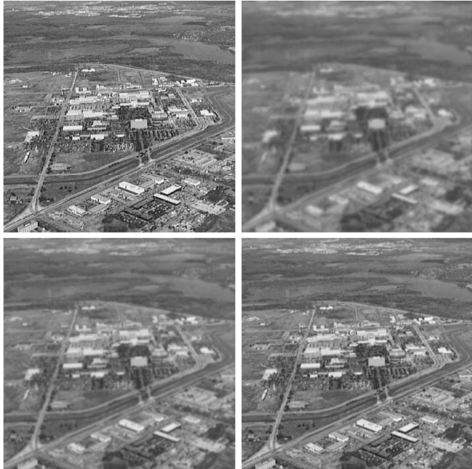
Image restoration is a significant aspect of image processing, aiming to recover an original image that has been degraded or corrupted by factors like noise, blurring, or distortion. Among various techniques used for image restoration, inverse filtering is one of the most straightforward and commonly used methods, especially for removing the effects of blurring. This article explains the mathematical concepts behind inverse filtering, the steps involved in the process, and examples to illustrate its practical application.
1. Degradation Model
The degradation of an image can be mathematically represented by a degradation model. The general degradation model is described by:
Where:
- is the degraded image.
- is the original image (unknown).
- is the degradation function, also called the point spread function (PSF) or blurring filter.
- represents the noise added to the image.
- denotes convolution.
In the frequency domain, the above model can be rewritten using the Fourier transform:
Where:
- , , and are the Fourier transforms of , , and respectively.
- is the Fourier transform of the noise .
- denotes pointwise multiplication.
1.1. Blurring Degradation
In real-world applications, blurring is a common type of degradation and is modeled by the degradation function . For example, motion blur and Gaussian blur are frequently used degradation types. In this context, the goal of inverse filtering is to recover the original image from the blurred image by reversing the effect of the degradation function .
2. Inverse Filtering Concept
The basic idea of inverse filtering is to reverse the degradation process by dividing the degraded image by the degradation function in the frequency domain.
Given the degradation model in the frequency domain:
The inverse filter tries to recover by simply dividing by :
Where is the estimate of the original image’s Fourier transform.
The recovered image can then be obtained by applying the inverse Fourier transform to .
2.1. Challenges in Inverse Filtering
While the concept of inverse filtering seems simple, it faces practical difficulties:
Noise Sensitivity: Inverse filtering amplifies any noise , especially if has very small values or zeros. This is because dividing by small values results in large values, leading to significant noise amplification.
Ill-conditioning: If is close to zero for some frequencies, division by such small values causes instability and unreliability in the reconstruction.
3. Example of Inverse Filtering
3.1. Problem Setup
Let’s assume a 1D image signal is blurred by a known degradation function , and the observed image is:
3.2. Frequency Domain Representation
The Fourier transforms of the functions , , and are:
Using inverse filtering, we can estimate the original image in the frequency domain:
Finally, the original image can be recovered by performing the inverse Fourier transform of .
3.3. Example
Suppose the degradation function is a simple Gaussian blur with known parameters. After applying the inverse filter to the blurred image, we would use the Fourier transforms of both the degraded image and the blur function to estimate the original image.
Let’s say:
- The degradation function in the frequency domain has small values at high frequencies.
- The Fourier transform of the observed image is known.
After applying the inverse filter, the high-frequency noise in the image may be amplified, resulting in a noisy restored image. This is a known limitation of inverse filtering, leading to the development of regularized filtering or Wiener filtering to address these issues.
4. Improving Inverse Filtering with Regularization
Due to the noise sensitivity and ill-conditioning issues in inverse filtering, more advanced methods are often used to stabilize the solution. One such method is Wiener filtering, which incorporates regularization and reduces the effect of noise.
The Wiener filter modifies the inverse filtering formula to include both the degradation function and the noise characteristics, leading to a more stable solution.
Wiener Filter Formula:
Where:
- is the complex conjugate of the degradation function.
- and are the power spectral densities of the noise and the original image, respectively.
This filter optimally balances the inverse filtering solution by minimizing the effect of noise.


Practical Example of Inverse Filtering
The image in Figure 5.25(b) was inverse filtered using the degradation function defined as:
Where:
- ,
- (image size),
- is a Gaussian-shaped function with no zeros, meaning no division by zero occurs.
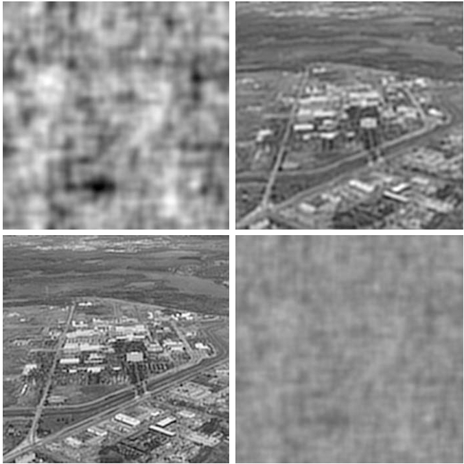
However, even though the degradation function had no zeros, the result of full inverse filtering, as seen in Figure 5.27(a), was poor. The degradation caused by noise became more significant than the restoration benefits, leading to a highly noisy result.
3.1. Filtering with Cut-Off Frequencies
To mitigate the influence of small values of , a cutoff filter was applied at various radii (40, 70, and 85) from the origin in the frequency domain. This limited the inverse filtering to low frequencies where is more reliable.
The results for different cutoff values are shown:
- Figure 5.27(b) (cutoff radius = 40): The result is slightly better than the full inverse filter but remains blurred.
- Figure 5.27(c) (cutoff radius = 70): The best visual result was obtained here, where the image appears more detailed with less noise.
- Figure 5.27(d) (cutoff radius = 85): The image is degraded again, with noise overtaking the visual content.
4. Limitations of Direct Inverse Filtering
The results clearly demonstrate that direct inverse filtering is highly sensitive to noise. Even with a Gaussian degradation function that avoids zero values, the process of dividing by small values in amplifies noise significantly.
The primary limitation of inverse filtering is that it does not account for noise in the degradation model. Therefore, in practice, advanced techniques such as Wiener filtering (which balances the noise and restoration processes) are preferred for more robust image recovery.
Conclusion
Inverse filtering is a powerful technique in image restoration that leverages frequency domain analysis to reverse image degradation caused by blurring. However, the simplicity of the method comes with limitations, particularly its sensitivity to noise and poor performance in the presence of small values in the degradation function. To address these limitations, more advanced methods like Wiener filtering are often applied to produce stable and reliable image restorations.
References
- Gonzalez, R. C., & Woods, R. E. (2008). Digital Image Processing (3rd ed.). Pearson Prentice Hall.
- Jain, A. K. (1989). Fundamentals of Digital Image Processing. Prentice-Hall.
- Castleman, K. R. (1996). Digital Image Processing. Prentice-Hall.
- Lim, J. S. (1990). Two-Dimensional Signal and Image Processing. Prentice-Hall.
